Download the questionnaire and submit it to us
info@torch-air.com


Made in the USA
Scan the QR code or click on it to start a chat in WhatsApp



1, 2 or 3 contact stages, selected for the process duty.
Reference configurations: 500–10,000 CFM (approx. 850–16,990 m³/h). All characteristics
Price and lead time: on request, based on the selected configuration.


5-Year guarantee
Easy installation and operation
Over 10 years of service life
Eco Friendly
GET COST AND TIME ESTIMATE
Obtain the cost and timeline for the equipment’s delivery
By filling out this form, you agree to our personal data processing policy
VORTEX Centrifugal Wet Scrubber
Wet Dust Collection With Intensive Gas–Liquid Contact
Intensive gas–liquid contact for wet particulate collection and selected gas absorption duties.

Wet Scrubber Description
The Torch-Air VORTEX is a centrifugal wet scrubber for transferring industrial dust from a gas stream into a scrubbing liquid. Gas passes through a stationary swirler and drives the liquid into a rotating contact layer. The resulting mixing creates a large, continuously renewed interface between the gas and liquid.
VORTEX is primarily a wet particulate collector. It can also be engineered for absorption of selected soluble or reactive gaseous contaminants when the scrubbing liquid, chemistry and contact stages are matched to the duty. Dust capture and gas absorption are assessed separately.
The unit combines one or more contact stages with a liquid separation zone. Torch-Air can supply the scrubber vessel or develop a complete system with a recirculation tank, pumps, fan, piping and controls. Materials and access arrangements are selected for the gas composition, temperature, abrasion and maintenance requirements.
VORTEX is primarily a wet particulate collector. It can also be engineered for absorption of selected soluble or reactive gaseous contaminants when the scrubbing liquid, chemistry and contact stages are matched to the duty. Dust capture and gas absorption are assessed separately.
The unit combines one or more contact stages with a liquid separation zone. Torch-Air can supply the scrubber vessel or develop a complete system with a recirculation tank, pumps, fan, piping and controls. Materials and access arrangements are selected for the gas composition, temperature, abrasion and maintenance requirements.

Stationary contact elements
The swirler remains fixed. Gas energy drives the rotating gas–liquid layer, so the contact zone does not require a rotating shaft or drive.
Staged treatment
One, two or three contact stages can be specified to provide the contact required for the selected dust and absorption duty.
Integrated liquid separation
A downstream separation zone collects scrubbing liquid. Additional mist polishing can be included when the outlet specification requires it.
Improved Design for Customized Tasks From the Client
Process Integration and Materials

Vessel geometry, gas inlet arrangement and the surrounding equipment can be adapted to the available installation space.
Carbon steel, stainless steel, suitable polymers and specialist materials can be evaluated for chemical compatibility and abrasion resistance.
Fan, liquid circulation, drainage and controls can be coordinated around the operating duty and the plant interface.
Compact process integration
Materials for the process
Complete system scope
Design Features
Coaxial or tangential gas inlet
A top inlet chamber or a scroll-type distributor, according to the vessel configuration.
Positive pressure or vacuum
The unit can operate under both positive pressure and vacuum.
No spray nozzles to clog
Liquid enters the swirler through tangential slots, so liquid quality and inlet pressure are less critical than in nozzle-based systems.

Stable with changing gas flow
As gas flow increases, centrifugal forces grow and stabilize the rotating gas–liquid layer.
Parallel installation
Several units can be installed in parallel for higher flow rates.
VORTEX Configurations
One stage
For duties where one contact stage meets the required treatment target.
Two or three stages
For additional contact; fan selection must account for the higher total resistance.
Complete system
Scrubber with a separately defined liquid circuit, fan and control scope.
Spheres of Use
VORTEX is primarily a wet particulate collector and can be engineered for selected gas absorption duties.
- Industrial dust extractionWettable process dust from manufacturing and materials handling, subject to particle size, loading and liquid compatibility.
- Chemical processingCombined dust and selected soluble-gas duties using a suitable scrubbing solution and reagent control.
- Metallurgical process exhaustParticulate-bearing exhaust where wet treatment and the resulting wastewater can be accommodated.
- Process cooling and absorptionSpecially engineered heat and mass transfer duties, including cooling and selected component recovery.
Combustible or water-reactive dust, poorly soluble gases and high-temperature service require a duty-specific design. Wet dust collection does not establish suitability for every gas or dust mixture.
The Working Principle of VORTEX Scrubber
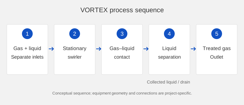
1. Gas and liquid enter. The contaminated gas enters the inlet chamber. Scrubbing liquid is supplied to the contact section through a separate liquid connection.
2. The stationary swirler creates rotation. Tangential passages impart rotation to the gas. The gas transfers momentum to the liquid and forms a rotating gas–liquid layer.
2. The stationary swirler creates rotation. Tangential passages impart rotation to the gas. The gas transfers momentum to the liquid and forms a rotating gas–liquid layer.
3. Contaminants transfer into the liquid. Particulate matter contacts the liquid and is collected. Suitable soluble or reactive gases may also transfer into the selected solution. Further contact stages are included where specified.
4. Liquid and gas separate. The mixture enters the separation zone. Collected liquid drains to the sump or recirculation system.
5. Treated gas leaves. The gas exits through the outlet after liquid separation. An optional final mist stage can be added to meet the selected outlet carryover target.
1 — Gas inlet · 2 — Liquid inlet · 3 — Swirler · 7 — Liquid outlet · 8 — Gas outlet.
Conceptual diagram. One-stage (left) and two-stage (right) arrangement.
4. Liquid and gas separate. The mixture enters the separation zone. Collected liquid drains to the sump or recirculation system.
5. Treated gas leaves. The gas exits through the outlet after liquid separation. An optional final mist stage can be added to meet the selected outlet carryover target.
1 — Gas inlet · 2 — Liquid inlet · 3 — Swirler · 7 — Liquid outlet · 8 — Gas outlet.
Conceptual diagram. One-stage (left) and two-stage (right) arrangement.

Inside the swirler
Horizontal cross-section of the stationary swirler: how the rotating gas–liquid layer forms.

1 Gas and liquid enter the swirler through tangential slots evenly spaced around the perimeter.

2 The gas starts to rotate and drives the liquid into rotation.

3 Centrifugal force presses the liquid outward into a rotating foam ring. The swirler itself does not rotate.

4 Gas and liquid move through the rotating layer along a spiral path toward the center, forming fine bubbles.
Specifications
Reference configurations and indicative pressure drops are selection information, not a performance guarantee. Final airflow, dimensions, pressure drop and equipment ratings are stated in the project specification.
Package
Basic package
The basic package is defined by the approved arrangement for the project.
VORTEX vessel with contact stages and swirlers
1
Access provisions and supports
Set
Gas and liquid connections, collection section, drain
Set
Project drawings and operating documentation
Set
Additional package elements
Options are selected with the client according to the gas, the required treatment and the plant interface.

MANAGEMENT AND CONTROL
- Reagent dosing and pH control for the selected absorption duty
- Liquid level, pressure-drop and flow monitoring
- Plant control interface

DESIGN AND FILTER
- Recirculation tank, pump and process piping
- Duty/standby pumps or fan, where required
- Additional mist separation or compatible final polishing
- Platforms, access steelwork and duct transitions
- Abrasion-resistant internal coating, which also reduces adhesion of sticky dust
Modifications and Sizes
VORTEX is supplied with one, two or three contact stages; additional arrangements are engineered for the project.
Reference configurations cover 500–10,000 CFM (approx. 850–16,990 m³/h). For higher flow rates, several units can be installed in parallel.
Final airflow, dimensions and connection positions are stated in the project drawings. The final supply scope and operating requirements are stated in the project specification.
Reference configurations cover 500–10,000 CFM (approx. 850–16,990 m³/h). For higher flow rates, several units can be installed in parallel.
Final airflow, dimensions and connection positions are stated in the project drawings. The final supply scope and operating requirements are stated in the project specification.
Scrubber Design
The VORTEX vessel houses the gas inlet chamber, the liquid inlet, one or more stationary swirlers made of inclined vanes arranged around the circumference, a liquid separation zone and a sump with a drain connection. Materials and access arrangements are selected for the gas composition, temperature, abrasion and maintenance requirements.
Operation and Maintenance
Inspect liquid flow, pressure drop, liquid level and drainage during operation. Maintain the liquid quality required by the process, remove accumulated solids and check contact passages for deposits or wear.
Cleaning intervals depend on loading and operating history; they are defined in the project operating instructions.
Cleaning intervals depend on loading and operating history; they are defined in the project operating instructions.
For process control, the package can include:
- Liquid level, pressure-drop and flow monitoring
- Reagent dosing and pH control
- Automatic make-up and drainage of the scrubbing liquid
- Connection of the scrubber controls to the plant control system
FAQ and Product Selection
No. The swirler is stationary. The gas stream drives rotation of the gas–liquid contact layer.
It collects suitable particulate matter by wet contact. Absorption of a gaseous contaminant depends on its solubility or reaction with the selected liquid and must be specified separately.
The swirler is fed without spray nozzles, so there are no nozzles to clog, and an internal coating can be specified to reduce dust adhesion. Suitability is confirmed for the specific dust during selection.
VORTEX includes a liquid separation zone. A further mist stage is selected when the required outlet carryover limit or downstream equipment calls for additional separation.
Other Products

Get a Consultation From One of Our Factory's Experts
Michael
Klepik
Klepik
Chief Executive Officer
Consults and provides calculations
Consults and provides calculations
Vladimir
Nikulin
Nikulin
Chief Technology Officer
Head of development and design
Head of development and design
+1 (918) 406-5684
info@torch-air.com
+1 (918) 406-5684
info@torch-air.com
DELIVERY AND INSTALLATION ALL OVER USA, CANADA, MEXICO
FULL ADHERENCE TO QUALITY STANDARDS
WE CUSTOMIZE INSTALLATIONS TO SUIT YOUR COMPANY
FAVORABLE PRICES FROM A US MANUFACTURER