Download the questionnaire and submit it to us
info@torch-air.com



Made in the USA
Scan the QR code or click on it to start a chat in WhatsApp



Author:
Michael Klepik, Chief Executive Officer
Michael Klepik, Chief Executive Officer

A waste gas treatment system at a stationary source is a chain of stages, each sized for one class of contaminant: particulate, acid components, VOCs or odor. Process vents from reactors, dryers, plating lines and tanks and combustion exhaust from boilers, kilns and incinerators use the same equipment in a different order. Engines are a separate field: on a diesel truck or vessel, what an exhaust gas after treatment system is comes down to an oxidation catalyst, a particulate filter and an SCR catalyst in series.
Design Basis
Understanding exhaust gas treatment systems starts with the data sheet. Equipment is sized on actual flow, while permits and stack tests use standard conditions:
acfm = scfm × (T + 460) / 528 × 14.7 / P
where T is in °F, P is in psia, and 528 °R equals 68 °F. At 20 % water vapor, wet flow is 25 % above the dry-basis figure.
Fabric filters and carbon beds must run above the dew point of every condensable; for acidic combustion exhaust, designers keep 25–50 °F over the acid dew point. Dust loading in gr/scf shows whether a cyclone or fabric filter must precede a wet stage, and solubility in water or caustic decides between absorption and adsorption. For solvent vapors, the adsorber inlet is normally held below 25 % of the lower explosive limit, calculated for the actual mixture: LEL is 1.1 % for toluene and 2.5 % for acetone.
An off-gas treatment system on a tank farm or reactor vent must also be checked at peak rate. Vapor displaced during filling equals the pumped liquid volume, so a tank filled at 300 gpm pushes out about 40 cfm.
acfm = scfm × (T + 460) / 528 × 14.7 / P
where T is in °F, P is in psia, and 528 °R equals 68 °F. At 20 % water vapor, wet flow is 25 % above the dry-basis figure.
Fabric filters and carbon beds must run above the dew point of every condensable; for acidic combustion exhaust, designers keep 25–50 °F over the acid dew point. Dust loading in gr/scf shows whether a cyclone or fabric filter must precede a wet stage, and solubility in water or caustic decides between absorption and adsorption. For solvent vapors, the adsorber inlet is normally held below 25 % of the lower explosive limit, calculated for the actual mixture: LEL is 1.1 % for toluene and 2.5 % for acetone.
An off-gas treatment system on a tank farm or reactor vent must also be checked at peak rate. Vapor displaced during filling equals the pumped liquid volume, so a tank filled at 300 gpm pushes out about 40 cfm.

Large-Scale Industrial Gas Treatment System with Scrubber and Baghouse Filter
Treatment Train Configuration
The order of stages depends on the chosen technology. A common wet train runs from dry particulate removal through quench and acid absorption to polishing of VOCs and odor. In a dry train, sorbent enters the duct ahead of the bags, which capture dust and acid together. Heavy dust goes ahead of any packed stage: according to EPA fact sheet EPA-452/F-03-015, packed-bed scrubbers are generally limited to particulate loadings below 0.20 gr/scf to avoid clogging. A wet stage leaves the stream saturated. The mist eliminator after it removes droplets, while water vapor passes through, so before a carbon bed the stream is reheated or diluted: above 75 % relative humidity, activated carbon can lose around 30 % of its VOC removal efficiency.
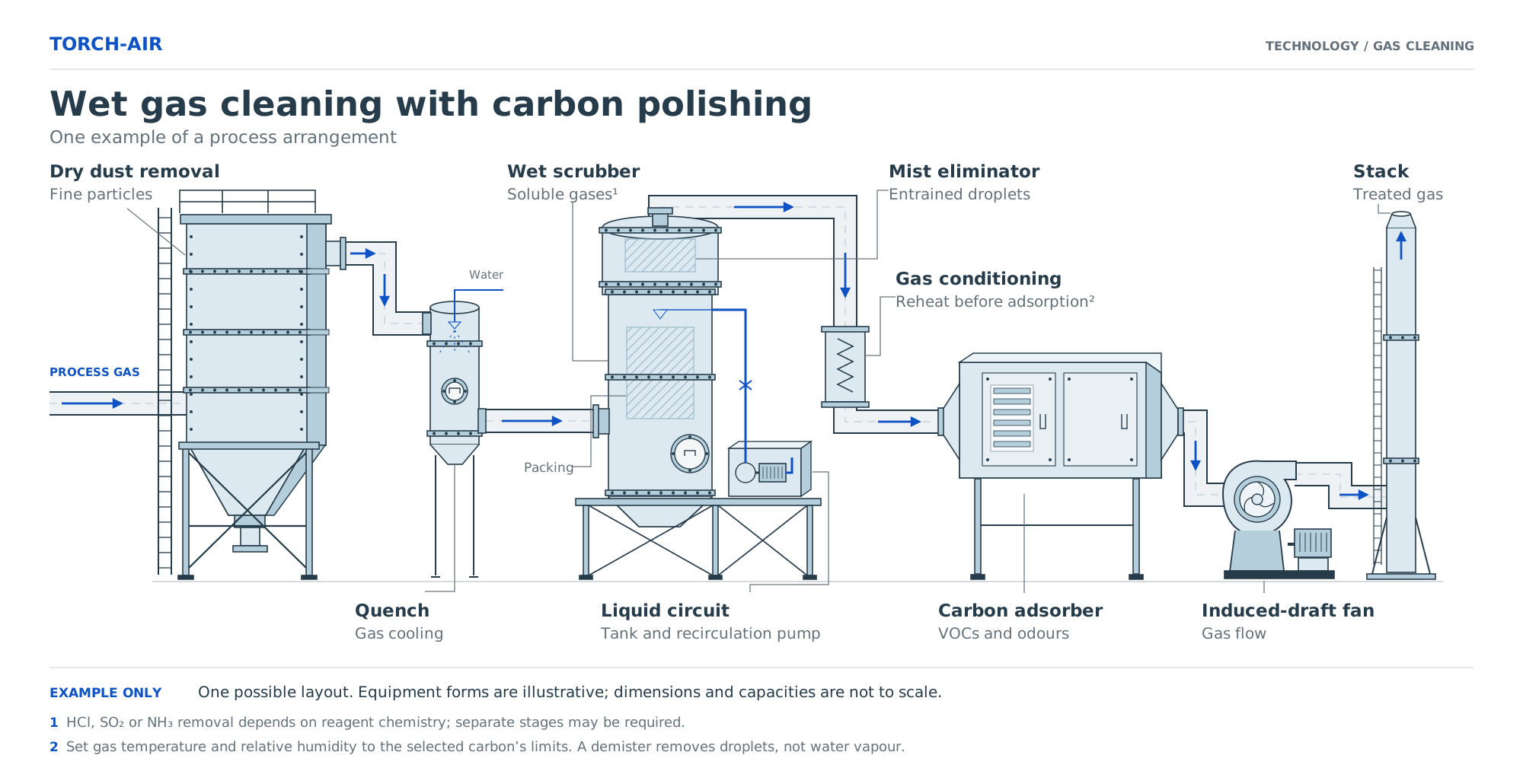
Wet cleaning train with carbon polishing: dry dust removal, quench, wet scrubber, mist eliminator, reheat, carbon adsorber, ID fan, stack.
At a gold mine, a Venturi scrubber on a diesel-fired concentrate dryer was started without the cyclones and bag filter specified ahead of it. Abrasive particles and sulfur wore out the carbon-steel Venturi tube, and the client reordered the unit in stainless steel with pre-filtration (case study). Such a dryer differs from an exhaust gas after treatment system on an engine: burner products mix with process dust upstream of any cleaning stage.
A dry flue gas treatment system for a boiler, kiln or small incinerator injects trona, sodium bicarbonate or hydrated lime into the duct and collects the reaction products with fly ash on a pulse-jet baghouse. The dust cake on the bags keeps reacting with SO₂ and HCl, so a baghouse removes more acid than an electrostatic precipitator at the same sorbent feed: typically 70–90 % SO₂ with trona versus 40–50 %. The reagent is stored in a silo vented through a silo filter.
Table 1. Typical trains by source
A dry flue gas treatment system for a boiler, kiln or small incinerator injects trona, sodium bicarbonate or hydrated lime into the duct and collects the reaction products with fly ash on a pulse-jet baghouse. The dust cake on the bags keeps reacting with SO₂ and HCl, so a baghouse removes more acid than an electrostatic precipitator at the same sorbent feed: typically 70–90 % SO₂ with trona versus 40–50 %. The reagent is stored in a silo vented through a silo filter.
Table 1. Typical trains by source

Animation of Baghouse Filter Operation
Equipment by Operating Principle
Table 2 lists the limits that usually decide the choice of media and materials.
Fabric and Cartridge Filtration
Pulse-jet baghouses and cartridge collectors capture particulate and solid sorbent products. A flue gas treatment system built around a bag filter is limited mainly by media. The Blizzard BIG covers 9,000–235,000 cfm with polyester, meta-aramid, PPS or anti-static bags, at 300 °F in standard form and up to 536 °F when modified. Cartridges fit lighter dust loads and cooler streams; oil mist and fine aerosols go to oil mist collectors.
Blizzard Bag Filter Review
Wet scrubbers
These units absorb soluble components and capture particulate in one vessel. The TORNADO SP packed tower (600–30,000 cfm) removes 99.5 % of HCl with caustic and of HF with water, and 99.9 % of NH₃ with water. In the TORNADO FB fluidized bed, plastic spheres up to 4 in. move constantly in the flow, so the unit accepts dust that would plug fixed packing. Venturi scrubbers handle heavy particulate and are usually followed by a packed or droplet-separation section.
Adsorption and Dry Scrubbing
Adsorbers polish VOCs, H₂S, NH₃ and residual odor after upstream stages remove the bulk load. Activated carbon handles most organics, impregnated carbons and chemisorbents bind H₂S, NH₃ and acid vapors, and a lime-based sorbent serves fluosilicic acid tank vents.
Biological Treatment
A biological gas treatment system oxidizes odorous and biodegradable compounds with microorganisms fixed on a moist bed. Biofilters remove aldehydes, organic acids and hydrogen sulfide without reagents, provided the bed holds 40–60 % moisture and a pH near 7. Contact times are long, so a biofilter needs far more floor area than a packed tower at the same flow. A wet pre-scrubber protects the bed from dust, acid peaks and dry air. Torch-Air builds biofilters to project specifications.
Overview | Air purification with biofiltration
System Sizing
The sequence below is for a dry train on a biomass boiler with illustrative inputs: 8,000 scfm (wet basis, 68 °F), 350 °F at the filter inlet, SO₂ 150 ppmv, milled trona injected upstream of pulse-jet bags.
- Actual flow: 8,000 × (350 + 460) / 528 ≈ 12,300 acfm.
- Cloth area at a conservative net air-to-cloth ratio of 4 ft/min, since sorbent adds dust load: ≈ 3,070 ft², or about 196 bags of 6 in. × 10 ft at 15.7 ft² each.
- SO₂ load: 150 × 10⁻⁶ × 8,000 × 60 / 385.3 ≈ 0.187 lbmol/h, or 12.0 lb/h. One mole of trona neutralizes 1.5 mol of SO₂, i.e. 2.35 lb of trona per lb of SO₂ at stoichiometry. EPA’s dry sorbent injection cost methodology assigns a normalized stoichiometric ratio of 1.5 to milled trona with a baghouse at 70 % SO₂ removal: 12.0 × 2.35 × 1.5 ≈ 42 lb/h, injected above 275 °F.
- Fan: add the pressure drops of the selected units from their data sheets (4–10 in. w.c. for a pulse-jet bag filter, Table 3), plus ducts and stack. In flue gas treatment systems with sorbent injection, bag pressure drop grows with reagent feed, so the fan is selected at the upper end of the range.
Operation and Monitoring
Differential pressure across each stage is the first trend to log. A baghouse creeping toward the top of its range points to blinding or failed diaphragm valves; a sudden fall means a torn bag. In wet stages, pH and ORP probes control caustic or oxidant dosing from reagent tanks, conductivity controls blowdown, and level control protects the recirculation pump. Rising pressure drop across a wet stage at constant liquid rate signals scale or plugged packing.
Carbon beds need outlet breakthrough monitoring; two beds in series let the lead bed run to saturation before change-out.
Corrosion appears wherever an exhaust gas treatment system runs below the acid dew point: during start-ups, in poorly insulated duct sections and at filter hoppers. Hopper heaters, insulation and a warm-up sequence before sorbent feed starts prevent most of these failures. Compliance is confirmed by stack tests such as EPA Method 5 (particulate) and Method 26A (hydrogen halides).
Carbon beds need outlet breakthrough monitoring; two beds in series let the lead bed run to saturation before change-out.
Corrosion appears wherever an exhaust gas treatment system runs below the acid dew point: during start-ups, in poorly insulated duct sections and at filter hoppers. Hopper heaters, insulation and a warm-up sequence before sorbent feed starts prevent most of these failures. Compliance is confirmed by stack tests such as EPA Method 5 (particulate) and Method 26A (hydrogen halides).
Join the Conversation!
Share your thoughts on this article, rate it, or spread the word by sharing it with others.
Your feedback is appreciated!
Share your thoughts on this article, rate it, or spread the word by sharing it with others.
Your feedback is appreciated!

We always perform precise calculations and offer expert assistance in selecting the optimal dust collection or gas cleaning systems, typically completing this process within 1 to 2 days
Head of Engineering,
Vladimir Nikulin
Vladimir Nikulin
CALCULATION AND SELECTION
After filling out this form, you will obtain the cost of the equipment and time frame over which it will be delivered


By filling out this form, you agree to our personal data processing policy
DELIVERY AND INSTALLATION ALL OVER USA, CANADA, MEXICO
FULL ADHERENCE TO QUALITY STANDARDS
WE CUSTOMIZE INSTALLATIONS TO SUIT YOUR COMPANY
FAVORABLE PRICES FROM A US MANUFACTURER

Operating in USA, Canada, and Mexico